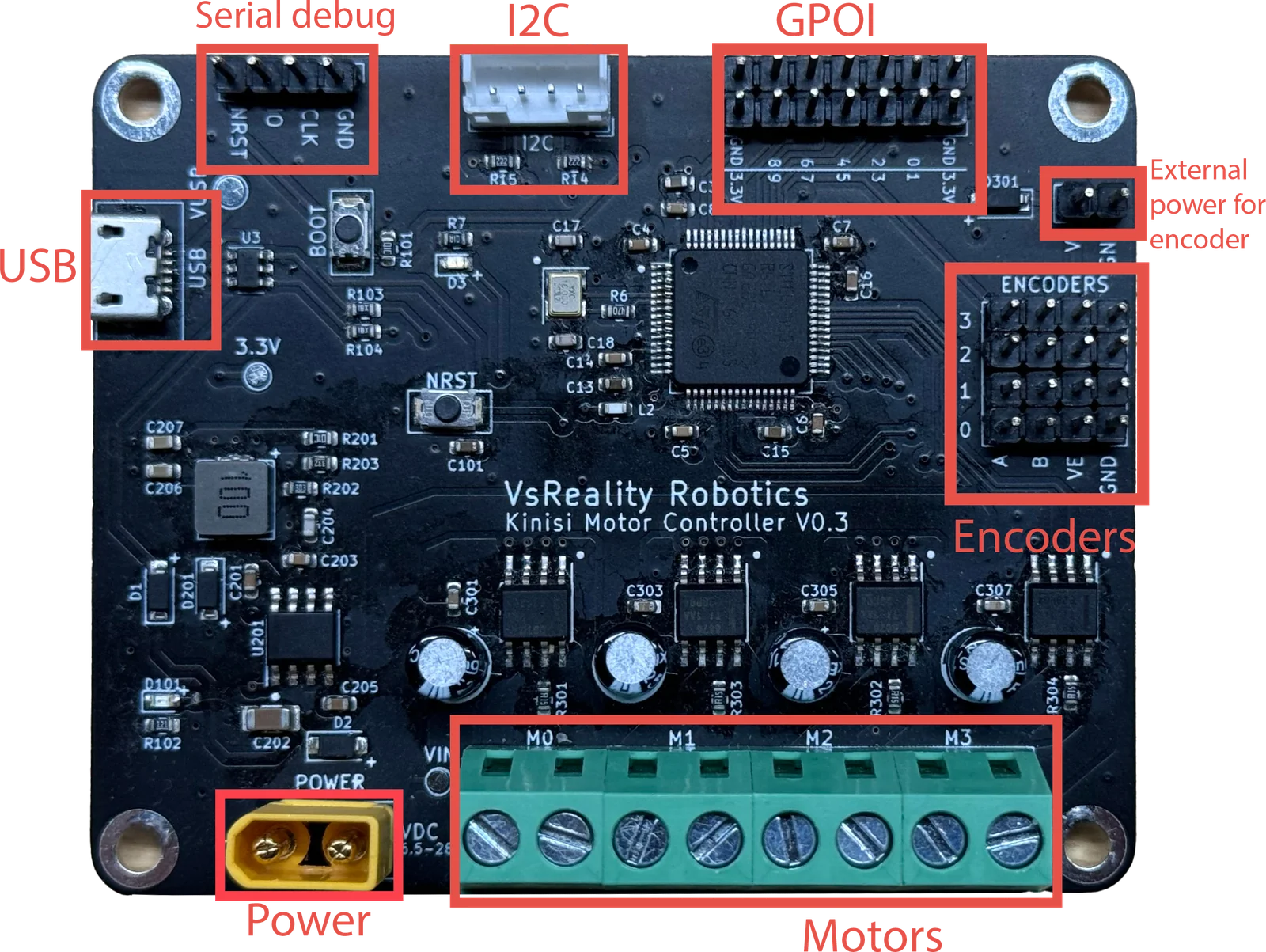
Purpose: This is the serial interface for the Kinisi Motor Controller. It allows you to send commands to the board from a computer or other USB-enabled device.
Usage: Connect a Micro USB cable from your computer to the controller for communication, firmware updates, or power (when powered via USB).
Specifications: Accepts DC input in the range of 6.5V to 28V.
Usage: This connector is used to supply power to the motor controller and connected motors. The XT30 connector is designed for higher current applications, ensuring stable power delivery.
Purpose: Provides a communication interface for sending commands to the board via I2C protocol, commonly used for interfacing with sensors and other peripherals.
Usage: Connect your I2C master device to this port to control the motor controller alongside other devices on the same bus.
Purpose: General-Purpose Input/Output (GPIO) pins can be configured for a wide variety of tasks, such as reading sensors, controlling LEDs, or other custom functions.
Usage: These pins can be programmed and utilized according to your project needs, making the controller versatile for different applications.
Purpose: Allows you to supply power to encoders that require a voltage higher than the board's native 3.3V.
Usage: Use this connector to provide the appropriate voltage directly to your encoders, ensuring they receive the necessary power without being limited to the 3.3V provided by the board.
Purpose: This interface is used for serial debugging, providing access to debugging information and allowing for troubleshooting.
Usage: Connect a serial interface to the pins labeled GND, CLK, IO, and NRST to monitor and debug the motor controller's operations. This is useful for development and diagnosing issues.