Command Documentation (v1.4.0)
This document provides comprehensive descriptions of all commands available in the system, along with their associated codes, detailed descriptions, properties, and response objects where applicable. Each section is categorized for easy reference.
Table of Contents
Motor Commands
INITIALIZE_MOTOR
- Code:
0x01 - Description: The
INITIALIZE_MOTORcommand is used to initialize a specific motor on the system, preparing it for operation. This involves setting up the motor's internal state and configuration, allowing it to respond to subsequent control commands. This command must be executed before any other motor-related commands to ensure proper functionality. - Category: Motor
- Properties:
motor_index(uint8_t): The index of the motor to initialize. Valid values range from 0 to 3, where each number corresponds to a different motor.is_reversed(bool): This property determines whether the motor's rotation direction should be reversed. By default, this is set tofalse, meaning the motor will rotate in the standard direction.
SET_MOTOR_SPEED
- Code:
0x02 - Description: The
SET_MOTOR_SPEEDcommand allows you to control the speed of a specified motor by providing a PWM (Pulse Width Modulation) value. This command directly influences the motor's output speed and direction, based on the PWM value provided. A positive value will spin the motor forward, while a negative value will reverse its direction. - Category: Motor
- Properties:
motor_index(uint8_t): Identifies which motor (from 0 to 3) you want to set the speed for.pwm(double): The PWM value that controls the motor speed. The value ranges from -100.0 to 100.0, where -100.0 represents full speed in reverse, 0 stops the motor, and 100.0 represents full speed forward.
STOP_MOTOR
- Code:
0x03 - Description: The
STOP_MOTORcommand is designed to immediately halt the specified motor by setting its speed to zero. This command is essential in situations where you need to stop motor movement quickly and safely, ensuring the motor remains stationary until further commands are issued. - Category: Motor
- Properties:
motor_index(uint8_t): Specifies the motor that should be stopped. The value ranges from 0 to 3.
BRAKE_MOTOR
- Code:
0x04 - Description: The
BRAKE_MOTORcommand activates the braking mechanism for the specified motor, which helps to bring the motor to a stop more rapidly than simply setting the speed to zero. This command is particularly useful in applications where precise stopping is critical, such as in robotics or automated machinery. - Category: Motor
- Properties:
motor_index(uint8_t): Identifies which motor to brake. The value ranges from 0 to 3.
Motor Controller Commands
INITIALIZE_MOTOR_CONTROLLER
- Code:
0x05 - Description: The
INITIALIZE_MOTOR_CONTROLLERcommand configures and initializes the motor controller for a specific motor. This command is crucial for enabling closed-loop control, where the motor's speed and position can be precisely managed using feedback from an encoder. The setup includes specifying the encoder to use, tuning the PID control constants, and setting limits on the controller's operation. - Category: Motor Controller
- Properties:
motor_index(uint8_t): Identifies the motor to be controlled. Valid range is 0 to 3.is_reversed(bool): Determines if the motor's direction should be inverted. Default isfalse.encoder_index(uint8_t): Selects the encoder associated with the motor. Range is 0 to 3.is_encoder_reversed(bool): Determines if the encoder's counting direction is inverted, independently ofis_reversed. Set this so that a positive commanded speed produces a positive measured speed (i.e. negative feedback). Default isfalse.encoder_resolution(double): Sets the resolution of the encoder in ticks per revolution. This value cannot be negative or zero.kp(double): The proportional constant of the PID controller, influencing how much the motor's output will change in response to a given error.ki(double): The integral constant of the PID controller, which helps to eliminate steady-state error by considering the cumulative sum of errors over time.kd(double): The derivative constant of the PID controller, which predicts future error based on its rate of change, helping to dampen the response.integral_limit(double): The maximum allowable integral value to prevent wind-up. If set to zero or negative, the integral part of the PID is effectively disabled.
SET_MOTOR_TARGET_SPEED
- Code:
0x06 - Description: The
SET_MOTOR_TARGET_SPEEDcommand is used to set the target rotational speed for a motor in radians per second. This command is particularly useful when precise control of motor speed is required, as it works in conjunction with the motor controller to maintain the specified speed despite changes in load or other variables. - Category: Motor Controller
- Properties:
motor_index(uint8_t): Specifies the motor for which the target speed should be set. Valid values range from 0 to 3.speed(double): The target speed in radians per second.
RESET_MOTOR_CONTROLLER
- Code:
0x07 - Description: The
RESET_MOTOR_CONTROLLERcommand resets the state of the motor controller associated with a specific motor. This command is useful for reinitializing the controller, clearing any errors, or returning it to a known state before reconfiguring or restarting the motor operation. - Category: Motor Controller
- Properties:
motor_index(uint8_t): Identifies which motor's controller to reset. Valid range is 0 to 3.
GET_MOTOR_CONTROLLER_STATE
- Code:
0x08 - Description: The
GET_MOTOR_CONTROLLER_STATEcommand retrieves the current state of the motor controller for a specified motor. This includes all relevant parameters such as PID constants, target speed, current speed, error, and output. This command is essential for monitoring the performance and status of the motor controller in real-time. - Category: Motor Controller
- Properties:
motor_index(uint8_t): Specifies the motor for which the controller state should be retrieved. Valid range is 0 to 3.
- Response:
motor_controller_state(object): An object containing detailed information about the current state of the motor controller, including PID constants, target speed, and current speed.
DELETE_MOTOR_CONTROLLER
- Code:
0x09 - Description: The
DELETE_MOTOR_CONTROLLERcommand removes the motor controller configuration for a specified motor. This effectively disables the controller, reverting the motor to manual control mode. Use this command when you no longer require closed-loop control for a motor. - Category: Motor Controller
- Properties:
motor_index(uint8_t): Identifies which motor's controller to delete. Valid range is 0 to 3.
SET_CONTROLLER_FREQUENCY
- Code:
0x0A - Description: The
SET_CONTROLLER_FREQUENCYcommand sets the global update frequency (in Hz) of the closed-loop motor controller task. All motor controllers share a single control loop, so this frequency is global and affects every running controller as well as any created afterwards; the PID sampling time is updated to match. The requested value is clamped to the supported range of 1 to 1000 Hz (the 1000 Hz maximum is bounded by the 1 ms RTOS tick) and quantized to whole milliseconds (period_ms = 1000 / frequency), so effective frequencies are 1000/N Hz. A value of 0 is invalid and ignored. Defaults to 10 Hz (100 ms) at start-up. - Category: Motor Controller
- Properties:
frequency(uint16_t): The controller update frequency in Hz. Valid range 1 to 1000 Hz; values outside are clamped, and 0 is ignored.
GET_CONTROLLER_FREQUENCY
- Code:
0x0B - Description: The
GET_CONTROLLER_FREQUENCYcommand retrieves the current global update frequency (in Hz) of the closed-loop motor controller task. - Category: Motor Controller
- Response:
frequency(uint16_t): The current controller update frequency in Hz (1 to 1000 Hz).
Encoder Commands
INITIALIZE_ENCODER
- Code:
0x11 - Description: The
INITIALIZE_ENCODERcommand sets up an encoder for use, configuring it with the appropriate resolution and direction. This command is a prerequisite for any operations that rely on encoder feedback, such as motor control or odometry calculations. - Category: Encoder
- Properties:
encoder_index(uint8_t): Specifies the encoder to initialize. Valid range is 0 to 3.encoder_resolution(double): Sets the resolution of the encoder in ticks per revolution. The value must be positive.is_reversed(bool): Determines if the encoder's direction is inverted. Default isfalse.
GET_ENCODER_VALUE
- Code:
0x12 - Description: The
GET_ENCODER_VALUEcommand retrieves the current value of the encoder, typically representing the number of ticks counted since the last reset or initialization. This value is crucial for determining the position or distance traveled by a motor or platform. - Category: Encoder
- Properties:
encoder_index(uint8_t): Specifies the encoder from which to retrieve the value. Valid range is 0 to 3.
- Response:
encoderValue(uint16_t): The current tick count of the encoder, representing its current position.
START_ENCODER_ODOMETRY
- Code:
0x13 - Description: The
START_ENCODER_ODOMETRYcommand begins the calculation of odometry data based on the encoder's readings. This is essential for tracking the movement and position of a robot or platform in relation to its starting point. - Category: Encoder
- Properties:
encoder_index(uint8_t): Identifies the encoder for which to start odometry calculations. Valid range is 0 to 3.
RESET_ENCODER_ODOMETRY
- Code:
0x14 - Description: The
RESET_ENCODER_ODOMETRYcommand resets the odometry calculations for a specific encoder, effectively setting the current position to zero. This command is useful when recalibrating or re-zeroing the position of a platform or motor. - Category: Encoder
- Properties:
encoder_index(uint8_t): Identifies the encoder for which to reset odometry. Valid range is 0 to 3.
STOP_ENCODER_ODOMETRY
- Code:
0x15 - Description: The
STOP_ENCODER_ODOMETRYcommand halts the ongoing odometry calculations for a specified encoder. Use this command when odometry data is no longer needed or before reconfiguring the encoder. - Category: Encoder
- Properties:
encoder_index(uint8_t): Identifies the encoder for which to stop odometry calculations. Valid range is 0 to 3.
GET_ENCODER_ODOMETRY
- Code:
0x16 - Description: The
GET_ENCODER_ODOMETRYcommand retrieves the current odometry data for the specified encoder, providing information on the distance traveled or position in radians. This is critical for applications requiring precise movement tracking. - Category: Encoder
- Properties:
encoder_index(uint8_t): Specifies the encoder from which to retrieve the odometry data. Valid range is 0 to 3.
- Response:
odometry(double): The current odometry value in radians, indicating the rotation or position tracked by the encoder.
SET_ODOMETRY_FREQUENCY
- Code:
0x17 - Description: The
SET_ODOMETRY_FREQUENCYcommand sets the global update frequency (in Hz) of the odometry task. A single odometry task integrates all encoder and platform odometry, so this frequency is global. The requested value is clamped to the supported range of 1 to 1000 Hz (the 1000 Hz maximum is bounded by the 1 ms RTOS tick) and quantized to whole milliseconds (period_ms = 1000 / frequency), so effective frequencies are 1000/N Hz. A value of 0 is invalid and ignored. Defaults to 20 Hz (50 ms) at start-up. - Category: Encoder
- Properties:
frequency(uint16_t): The odometry update frequency in Hz. Valid range 1 to 1000 Hz; values outside are clamped, and 0 is ignored.
GET_ODOMETRY_FREQUENCY
- Code:
0x18 - Description: The
GET_ODOMETRY_FREQUENCYcommand retrieves the current global update frequency (in Hz) of the odometry task. - Category: Encoder
- Response:
frequency(uint16_t): The current odometry update frequency in Hz (1 to 1000 Hz).
GPIO Commands
INITIALIZE_GPIO_PIN
- Code:
0x20 - Description: The
INITIALIZE_GPIO_PINcommand prepares a digital GPIO pin for operation, configuring it as either an input or output pin. This command is essential for setting up pins before using them in your application, whether for reading sensors or controlling devices. - Category: GPIO
- Properties:
pin_number(uint8_t): The number of the GPIO pin to initialize.mode(uint8_t): The mode to set for the GPIO pin. Modes: 0 = INPUT_PULLDOWN, 1 = INPUT_PULLUP, 2 = INPUT_NOPULL, 3 = OUTPUT.
SET_GPIO_PIN_STATE
- Code:
0x21 - Description: The
SET_GPIO_PIN_STATEcommand allows you to set the state of a GPIO pin, either turning it on (HIGH) or off (LOW). This command is typically used to control external devices like LEDs, relays, or other components connected to the GPIO pin. - Category: GPIO
- Properties:
pin_number(uint8_t): The number of the GPIO pin to set.state(uint8_t): The desired state of the pin. 0 = LOW, 1 = HIGH.
GET_GPIO_PIN_STATE
- Code:
0x22 - Description: The
GET_GPIO_PIN_STATEcommand reads the current state of a specified GPIO pin, returning whether it is currently HIGH or LOW. This is useful for monitoring the status of inputs like buttons or switches. - Category: GPIO
- Properties:
pin_number(uint8_t): The number of the GPIO pin to read.
- Response:
state(uint8_t): The current state of the pin. 0 = LOW, 1 = HIGH.
TOGGLE_GPIO_PIN_STATE
- Code:
0x23 - Description: The
TOGGLE_GPIO_PIN_STATEcommand flips the state of a GPIO pin from HIGH to LOW or from LOW to HIGH. This is particularly useful for creating simple toggling behaviors, such as blinking an LED. - Category: GPIO
- Properties:
pin_number(uint8_t): The number of the GPIO pin to toggle.
SET_STATUS_LED_STATE
- Code:
0x25 - Description: The
SET_STATUS_LED_STATEcommand controls the state of a status LED on the system, turning it on or off. This LED is often used to indicate the operational status of the system or to provide visual feedback for certain conditions. - Category: GPIO
- Properties:
state(uint8_t): The desired state of the status LED. 0 = OFF, 1 = ON.
TOGGLE_STATUS_LED_STATE
- Code:
0x26 - Description: The
TOGGLE_STATUS_LED_STATEcommand changes the current state of the status LED, turning it on if it was off, or off if it was on. This can be used to create visual indicators for system events or statuses. - Category: GPIO
Platform Commands
INITIALIZE_MECANUM_PLATFORM
- Code:
0x30 - Description: The
INITIALIZE_MECANUM_PLATFORMcommand configures a mecanum platform, preparing it for operation. This includes setting parameters such as motor direction, platform dimensions, and encoder resolution. This command is essential for ensuring the platform operates correctly in mecanum drive mode, allowing for omnidirectional movement. - Category: Platform
- Properties:
is_reversed_0(bool): Determines if motor 0 is reversed. Default:false.is_reversed_1(bool): Determines if motor 1 is reversed. Default:false.is_reversed_2(bool): Determines if motor 2 is reversed. Default:false.is_reversed_3(bool): Determines if motor 3 is reversed. Default:false.is_encoder_reversed_0(bool): Determines if encoder 0 counting direction is reversed (independent of motor). Default:false.is_encoder_reversed_1(bool): Determines if encoder 1 counting direction is reversed (independent of motor). Default:false.is_encoder_reversed_2(bool): Determines if encoder 2 counting direction is reversed (independent of motor). Default:false.is_encoder_reversed_3(bool): Determines if encoder 3 counting direction is reversed (independent of motor). Default:false.length(double): Length of the platform in meters. Default:1.width(double): Width of the platform in meters. Default:1.wheels_diameter(double): Diameter of the robot wheels in meters. Default:1.encoder_resolution(double): Encoder resolution in ticks per revolution. The value cannot be negative. If platform does not have encoders, the value should be set to zero. Default:0.
INITIALIZE_OMNI_PLATFORM
- Code:
0x31 - Description: The
INITIALIZE_OMNI_PLATFORMcommand sets up an omni-directional platform, configuring its motors, dimensions, and encoder parameters. This command is critical for ensuring the platform can perform precise movements in any direction, using omni-wheels. - Category: Platform
- Properties:
is_reversed_0(bool): Determines if motor 0 is reversed. Default:false.is_reversed_1(bool): Determines if motor 1 is reversed. Default:false.is_reversed_2(bool): Determines if motor 2 is reversed. Default:false.is_encoder_reversed_0(bool): Determines if encoder 0 counting direction is reversed (independent of motor). Default:false.is_encoder_reversed_1(bool): Determines if encoder 1 counting direction is reversed (independent of motor). Default:false.is_encoder_reversed_2(bool): Determines if encoder 2 counting direction is reversed (independent of motor). Default:false.wheels_diameter(double): Diameter of the robot wheels in millimeters. Default:1.robot_radius(double): Distance between the center of the robot and the center of the wheels in millimeters. Default:1.encoder_resolution(double): Encoder resolution in ticks per revolution. The value cannot be negative. If platform does not have encoders, the value should be set to zero. Default:0.
Wheel and axis layout
The three omni wheels are arranged 120° apart. The platform uses a
REP-103 right-handed frame: +x
points forward, +y points left, and +t is a counter-clockwise rotation.
The forward axis bisects motors M0 (front-right) and M1 (front-left), with
M2 at the rear.
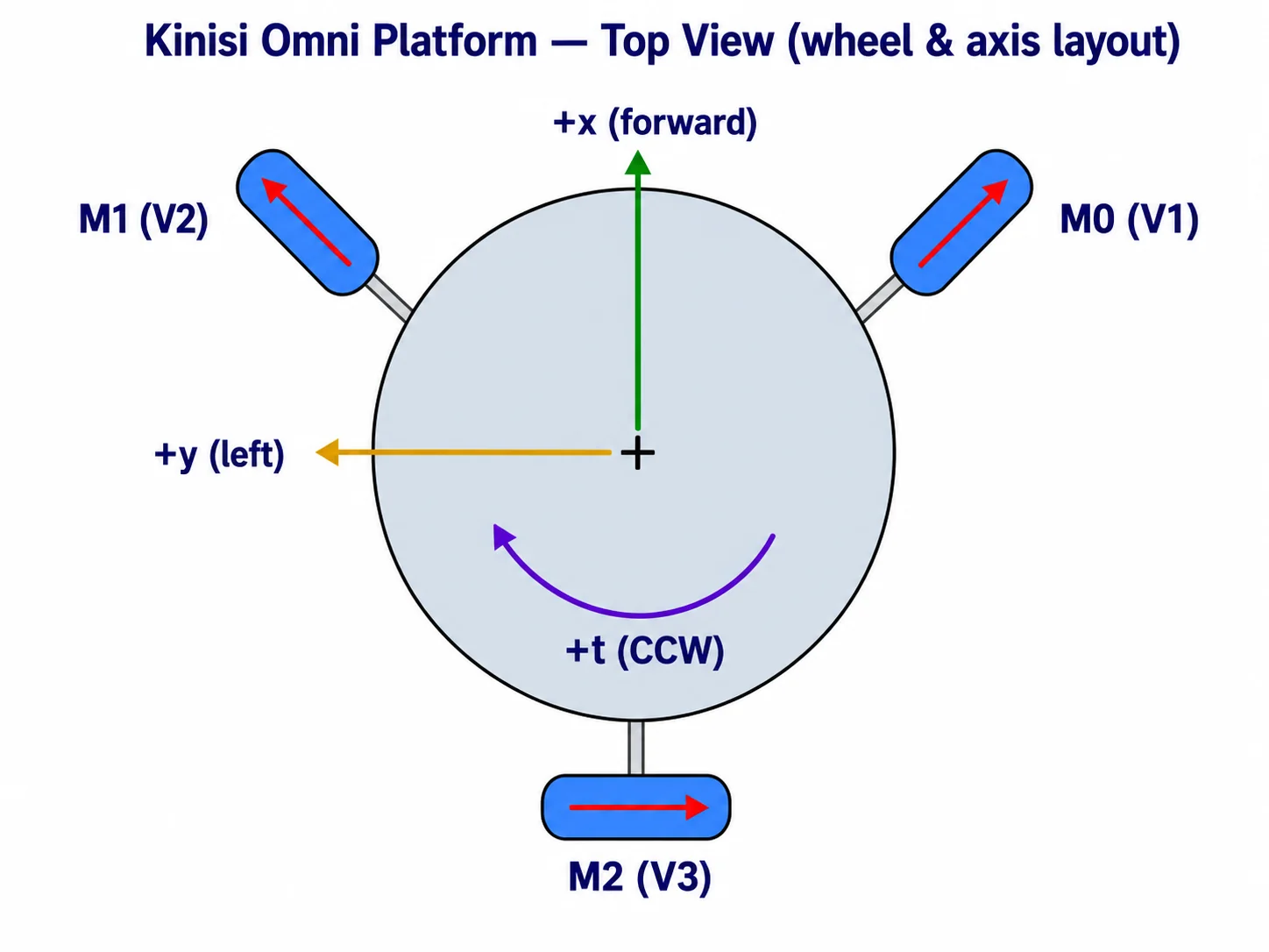
For a pure forward command (+x), V1 > 0, V2 < 0, and V3 = 0 (the rear
wheel idles). When a wheel is mounted with a reversed motor, reverse its
encoder as well so the velocity-controller feedback keeps the correct sign.
INITIALIZE_DIFFERENTIAL_PLATFORM
- Code:
0x32 - Description: The
INITIALIZE_DIFFERENTIAL_PLATFORMcommand sets up a differential (2-wheel) platform and prepares it for use. It uses motor and encoder index 0 for the left wheel and index 1 for the right wheel. Motor indices 2 and 3 are not used by this platform and stay free for other purposes. - Category: Platform
- Properties:
is_reversed_0(bool): Determines if motor 0 (left wheel) is reversed. Default:false.is_reversed_1(bool): Determines if motor 1 (right wheel) is reversed. Default:false.is_encoder_reversed_0(bool): Reverses encoder 0 counting direction, independently of motor 0. Set so the closed-loop feedback is negative. Default:false.is_encoder_reversed_1(bool): Reverses encoder 1 counting direction, independently of motor 1. Set so the closed-loop feedback is negative. Default:false.wheel_diameter(double): Diameter of the robot wheels in meters.wheel_base(double): Distance between the two wheels in meters.encoder_resolution(double): Encoder resolution in ticks per revolution. The value cannot be negative. If platform does not have encoders, the value should be set to zero.
SET_PLATFORM_VELOCITY
- Code:
0x40 - Description: The
SET_PLATFORM_VELOCITYcommand controls the velocity of a platform in terms of PWM values. This command allows for precise control of movement along the X and Y axes, as well as rotation (theta), enabling complex maneuvers for both mecanum and omni-directional platforms. - Category: Platform
- Properties:
x(double): X component of platform velocity in PWM. Range: -100.0 to 100.0.y(double): Y component of platform velocity in PWM. Range: -100.0 to 100.0.t(double): Theta component of platform velocity in PWM. Range: -100.0 to 100.0.
START_PLATFORM_CONTROLLER
- Code:
0x41 - Description: The
START_PLATFORM_CONTROLLERcommand starts the closed-loop PID controller for the platform, enabling precise control of its velocity using encoder feedback. Configure the platform (and its encoders) before starting the controller, then command motion withSET_PLATFORM_TARGET_VELOCITY. - Category: Platform
- Properties:
kp(double): Proportional constant of the PID controller.ki(double): Integral constant of the PID controller.kd(double): Derivative constant of the PID controller.integral_limit(double): Integral limit of the PID controller. The value cannot be negative. If zero or negative, the integral limit is disabled.
SET_PLATFORM_TARGET_VELOCITY
- Code:
0x42 - Description: The
SET_PLATFORM_TARGET_VELOCITYcommand sets the target velocity of the platform in real-world units, using the closed-loop platform controller. Requires the platform controller to be running (seeSTART_PLATFORM_CONTROLLER). - Category: Platform
- Properties:
x(double): X component of platform velocity in meters per second.y(double): Y component of platform velocity in meters per second.t(double): Theta component of platform velocity in radians per second.
GET_PLATFORM_CURRENT_VELOCITY
- Code:
0x43 - Description: The
GET_PLATFORM_CURRENT_VELOCITYcommand retrieves the platform's current velocity in real-world units, as estimated from encoder feedback. - Category: Platform
- Response:
platform_velocity(object): The current velocity of the platform in meters per second (and radians per second for rotation).
STOP_PLATFORM_CONTROLLER
- Code:
0x44 - Description: The
STOP_PLATFORM_CONTROLLERcommand stops the platform's closed-loop controller, halting closed-loop motion. Restart it withSTART_PLATFORM_CONTROLLERto resume closed-loop control. - Category: Platform
START_PLATFORM_ODOMETRY
- Code:
0x45 - Description: The
START_PLATFORM_ODOMETRYcommand starts odometry calculation for the platform, tracking its pose (position and heading) in the world frame from encoder feedback. - Category: Platform
RESET_PLATFORM_ODOMETRY
- Code:
0x46 - Description: The
RESET_PLATFORM_ODOMETRYcommand resets the platform's odometry, setting the current pose back to the origin. - Category: Platform
STOP_PLATFORM_ODOMETRY
- Code:
0x47 - Description: The
STOP_PLATFORM_ODOMETRYcommand stops odometry calculation for the platform. - Category: Platform
GET_PLATFORM_ODOMETRY
- Code:
0x48 - Description: The
GET_PLATFORM_ODOMETRYcommand retrieves the platform's current odometry (pose) in meters and radians. - Category: Platform
- Response:
platform_odometry(object): The odometry of the platform in meters and radians.
BRAKE_PLATFORM
- Code:
0x49 - Description: The
BRAKE_PLATFORMcommand actively brakes all of this platform's wheel motors (short brake) so they resist motion and hold position, and stops the platform velocity controller if it is running (callSTART_PLATFORM_CONTROLLERagain to resume closed-loop control). Motors used outside this platform are not affected. The motors resist motion until a new command is issued. - Category: Platform
COAST_PLATFORM
- Code:
0x4A - Description: The
COAST_PLATFORMcommand lets all of this platform's wheel motors coast freely (high impedance) so they spin down without resistance, and stops the platform velocity controller if it is running (callSTART_PLATFORM_CONTROLLERagain to resume closed-loop control). Motors used outside this platform are not affected. - Category: Platform